In addition to periodic inspections, certain safety features can facilitate or supplement the monitoring of overheating.
The offer is varied and there is no shortage of solutions. Depending on requirements, it is possible to invest in these solutions at the time of the initial investment or to equip the installations afterwards to save on inspection time while ensuring permanent and, therefore, more reliable monitoring.
Investing in active safety solutions from the moment of purchase
Choosing to install active safety elements allows for continuous thermal monitoring.
Why choose active safety solutions?
These safety components provide three major advantages:
- They permanently monitor the installation, unlike one-off campaigns, which do not guarantee to prevent a fault.
- They make it possible to remove thermography campaigns from the planning schedule. The maintenance teams' schedule is lightened and they can devote themselves to other activities.
- They prevent your employees from taking risks: manual thermography carried out on open switchgear, near live parts, is always more risky from the point of view of a possible threat from an internal arc event. To ensure the safety of those involved suitable personal protective equipment is essential but sometimes cumbersome.
The initial investment on this type of solution is a little higher but it reduces the risk taken by your employees during interventions, the operating costs and the risk of immobilisation of your installation.
The 2 types of solutions to monitor the temperature of the electrical switchboard
 The active safety elements monitoring the temperature of the switchboard components are varied, they can be selected for certain zones only or completely equip the switchboard and thus cover the entire requirement.
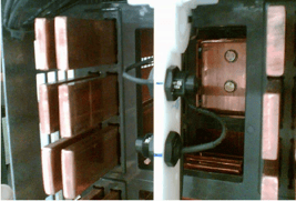
1. Heat monitoring by contact
Contact solutions are realised by strategically placed PT100 probes. These points are defined by the results of the IEC 61439-2 design verification tests and are installed by the original manufacturer. The probes give a reliable indication of the temperature at the measuring point and require a wired connection to a measuring transmitter. These links can be considered as bringing an additional risk in terms of insulation (min. 6kV) and internal arcing.
There are devices that are self-powered by the passage of current through the conductors, which report by wireless link. It should be noted that some circuit-breakers are already or can be equipped with solutions for monitoring their temperature at the poles and this information can also be reported remotely.
Withdrawable feeders can be equipped with a solution that monitors the temperatures of the upstream and downstream power connections by contact. These feeders report via a communication link all temperature and even current imbalance information. Each individual system can be configured so that the alarm or trip thresholds correspond exactly to the configuration of the feeder and its’ operating characteristics
Other more expensive solutions are used, particularly in high-voltage applications, and rely on fibre optics to report measurement information remotely.
Example of a sensor relay solution
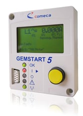 If the motor feeders are equipped with motor protection relays, the PTC input of the product generates an alarm when the ambient temperature of the drawer reaches a threshold considered critical.
The RTD extension module can be used to provide 6 PT100 probes for measuring ambient or surface temperatures in specific areas of the electrical panel.
The temperature alert is displayed on the local display, on the computer and can be received by email or sms.
Photo: GemStart motor protection relay for temperature rise monitoring
2. Monitoring of heat build-up by infrared sighting
 Infrared sighting measurement solutions are easy to implement. They are small sensors, 12mm in diameter and a few centimetres long, positioned a few centimetres away from the target area equivalent to a coin. They report the temperature difference between the ambient temperature and the targeted area.
Placed on supports, they allow non-contact monitoring:
- the joints of a main busbar
- upstream and downstream connections on open circuit breaker poles which are difficult to access
- the connection area of the switchboard power supply cables
The measurements are then collected on a transmitter transmitting results continuously via a communication link operated by a supervisor.
Modernise its installation to monitor overheating
For existing installations not equipped with monitoring devices, it is possible to retrofit, with or without switchboard disconnection, to benefit from the advantages of continuous temperature monitoring.
The drawers can be individually equipped with:
- a front opening system
- a sighting inspection window
- a temperature monitoring system on the power connections
This improvement is carried out quickly and the feeder concerned is only unavailable during the intervention.
If a circuit breaker already has intrinsic functionality for measuring the temperature of its’ poles and is communicating, only an intervention in the communication system allows the temperatures to be retrieved from the data table and used in the supervision software.
The installation of non-contact infrared sensors is an operation in the vicinity of live parts, so it is an operation to be carried out off-line for safety reasons.
In summary
You can anticipate the continuous monitoring of overheating when you purchase your new switchboard by using active safety solutions or modernise your existing installation by adding communicating equipment.
Active safety solutions using contact or infrared sighting provide continuous temperature measurement. They ensure the safety of operators by anticipating possible overheating of electrical panels.
In addition to safety, there are odour or smoke detection devices. They continuously analyse a volume of air aspirated in via cannulas arranged in each column of the panel and give a very early warning of any abnormal heating.